
Case study 01 · 2021 → present · Technotonin Industries
PAWE. Powered mobility. The chair you already know.
A detachable power-assist for compatible folding manual wheelchairs. It attaches in seconds, lifts off for transport, and fits in a car trunk. I co-founded PAWE with Arav Tyagi and developed its mechanics, electronics, and firmware, guided by feedback from wheelchair users and clinicians.
- 15 lb device
- 6 mph top speed
- ~10 mi range
- 10 s to attach
- $1,500 target vs $5–10K chairs
- US 12,605,293 granted
Why it exists
Friends with muscular dystrophy needed power chairs they could not afford — and could not get into a car.
Cost and transport were the problems we wanted to solve: how could someone add powered mobility to their existing chair and still take it in a car? Arav Tyagi and I started in a garage in 2021 with about $50 of gearboxes, parts donated by our robotics club, and a wheelchair donated by a senior center.
Everything since has been shaped by over 100 interviews with wheelchair users, caretakers and clinicians, and by demo days at the Bellingham and Franklin senior centres where people drove it and told us what was wrong with it.
- Two friction rollers press against the chair's rear tires; torque transfers by friction. No chair modification.
- Hot-swap battery clicks in and out by hand, so the pack rides in a bag and the chair stays light.
- Modular controller — joystick or push-assist, speed-capped per user, with alternative inputs (eye-tracking, tongue-drive) contemplated in the patent claims.
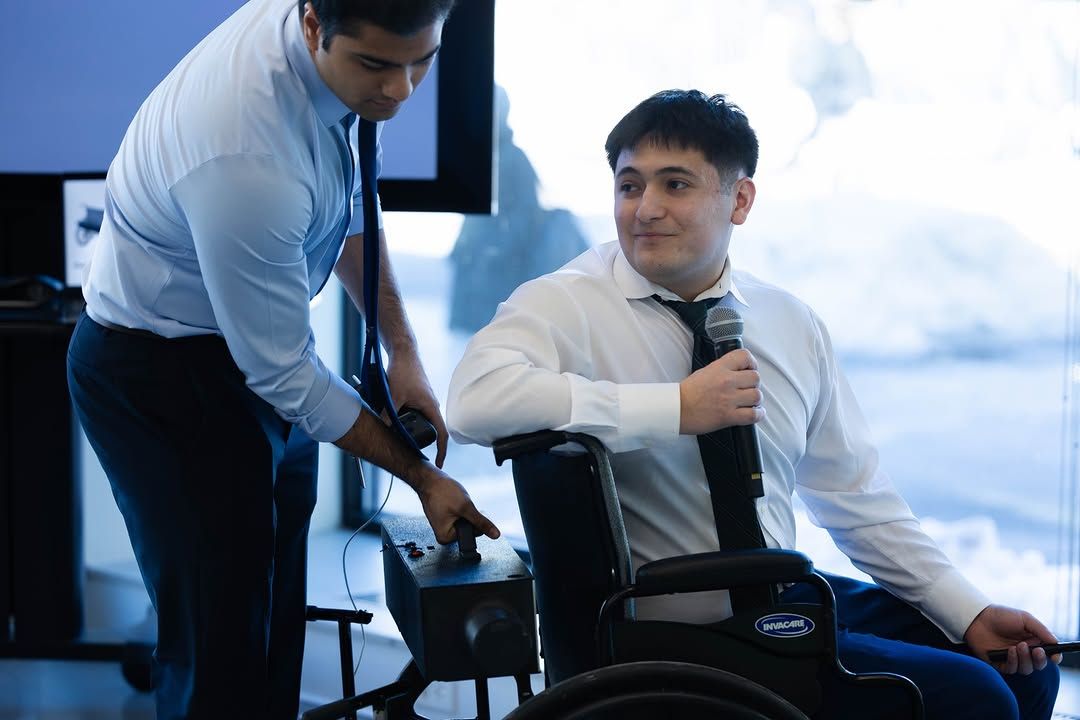
Technotonin Industries. Co-founders Antonio Marzoratti and Arav Tyagi. Mentors include Scott Harris, co-founder of SolidWorks and Onshape.
Specification
The design at a glance.
Published specifications, design targets, and their supporting sources.
| Specification | Value | Basis |
|---|---|---|
| Device mass | 15–17 lb confirmation pending | Published figures differ; a consistent measured weight is pending. |
| Top speed | 6 mph | User-adjustable; 3 mph standard mode |
| Range per charge | ~10 mi | Product site; local press has reported 8 mi |
| Attach time | ~10 s | Three-step align-and-lock, no tools |
| Compatible chairs | 16–22 in folding frame | Invacare, Drive, Karman, Medline tested; rigid frames in development |
| Rated user mass | 136 kg / 300 lb | As described in the FDA Pre-Submission |
| Incline | 6° (10 %) | Clears most ADA-compliant grades |
| Battery | LiFePO₄ 4S · 12.8 V · 20 Ah | Integrated BMS; hot-swappable |
| Motors | 2 × MY1016, 250 W | 24 V brushed, run at ~12.8 V |
| Drive ratio | 1 : 1 direct | Roller on the motor output shaft — no chain, belt or gearbox |
| Ingress | IPX4 | Design target |
Mechanism · US 12,605,293
Dual-motor differential friction drive, and the patent that covers it.
Each rear tire gets its own 250 W motor with a compliant roller pressed against the tread. Independent per-side torque and rotational-velocity control means the same two rollers drive, steer and brake — there is no steering mechanism, just a difference in wheel speed.
The contact patch is the whole problem. A rigid roller slips in the wet; a soft one deforms and heats. The claimed solution is a flexible polymer ring backed by rigid polylactic-acid fillers — compliant where it meets rubber, stiff where it carries torque.
- Claim 1 — two motors on shafts to rotatable ends, a driver per motor, flexible rings between ring and shaft, a controller carrying torque and velocity data, mounted behind the seat.
- Claim 10 — the polymer ring with rigid PLA fillers.
- Claim 12 / 17 — the PWM processor architecture and the integrated housing with independent motor control.
- Filed 22 Feb 2023 · granted 21 Apr 2026 · 19 claims · first-named inventor · assigned to Technotonin Industries LLC.
Independent per-side control. Steering is a speed difference between the rollers. The one number nobody has measured yet — the clamp force at the roller — is flagged [?], because the simulation results hinge on it.
Electronics
Inside the power system.
Both boards were designed from schematic capture through complete fabrication and assembly packages. Every net in the as-built documentation carries a tag saying how it was verified: measured, flashed-firmware fact, observed, datasheet-cited, or unknown.
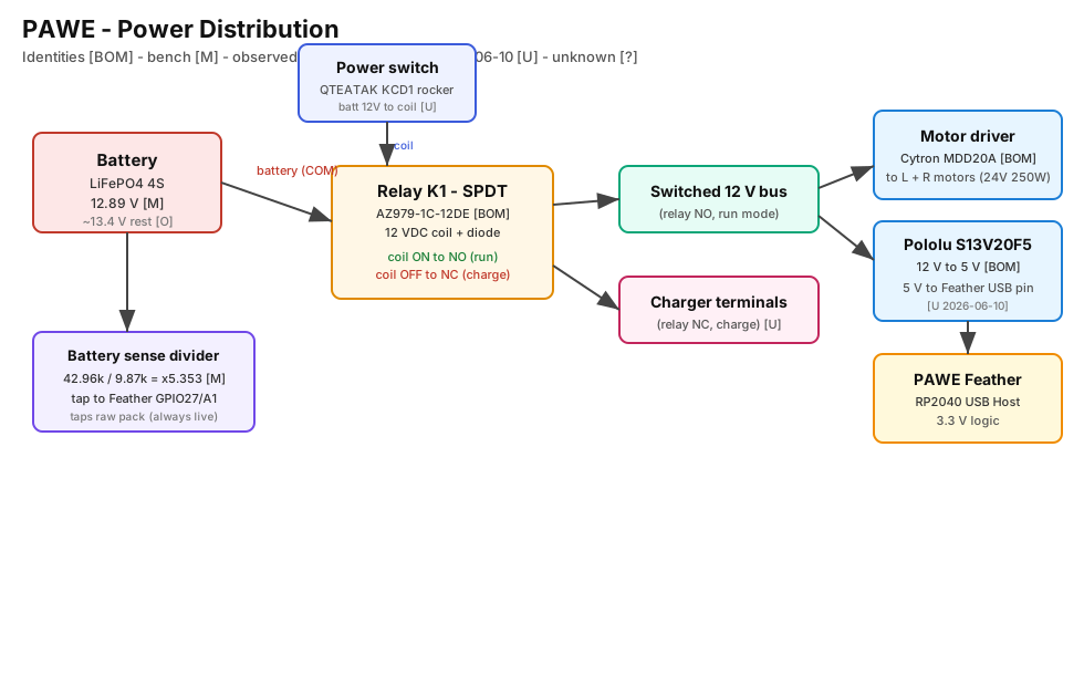
Power tree. LiFePO₄ pack → BMS → illuminated rocker → run/charge relay → switched 12 V bus → Cytron MDD20A dual driver and a Pololu buck-boost for the 5 V logic rail. Always-live battery-sense divider into a 12-bit ADC.
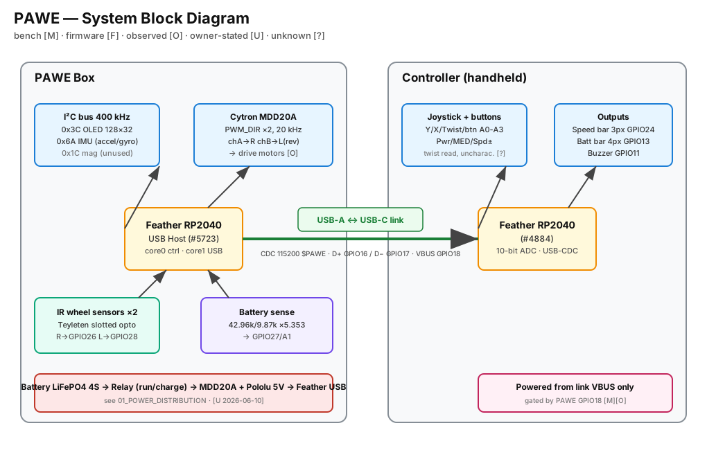
System block. Chassis RP2040 as USB host (PIO-USB on core 1, 120 MHz) talking to the joystick RP2040 over one cable that also powers it. OLED, IMU and two IR wheel sensors on the chassis side.
A BMS cut also kills the relay coil
The relay coil is fed from the raw pack through the rocker, so a BMS over-current cut drops the relay to the charger position, the load disconnects, and a load-detecting BMS re-closes. The system can cycle instead of staying safely off. Found in simulation, now a design item.
Pack sag cannot glitch the logic rail
The 5 V rail comes off a buck-boost good down to 2.8 V in. Worst corner (60 mΩ source, 5 % SOC, doubled wiring resistance) still leaves ~9.6 V at the pack and ~7.1 V at the driver bus — above every UVLO in the chain.
Motor current can exceed battery current
During the PWM-off freewheel the motor current circulates in the bridge, so average battery current is duty × motor current. Clamp the meter on the wrong lead and you under-read the motors by the duty cycle.
Firmware & control
Two MCUs, one cable, and a control loop I chose to retire.
The joystick is the master; the chassis is the slave. They talk over USB-C with a framed, checksummed ASCII protocol ($PAWE,ver,type,…*CK), with a link-loss recovery state machine and a motors-off failsafe if the cable is pulled. At PWM = 0 the driver actively brakes, so if the MCU dies the chair stops rather than coasts.
The closed-loop stack (June 2026)
- Gain-scheduled PID — separate low- and high-speed gain sets blended by measured speed; integral clamp expressed in output units so it survives retuning; back-calculation anti-windup that undoes the specific integral step that saturated.
- Gyro heading-hold — LSM6DS3TRC gyro-Z at 104 Hz; 1.2 s power-on bias average, then continuous still-time bias trimming on a ~2 s time constant whenever the rate stays under 0.7°/s for 250 ms. Engages only when both wheels agree on direction, magnitude and speed, and corrects as a differential nudge so speed never changes.
- Dual-τ smoothing — separate time constants for driving vs letting go or reversing, so stops feel crisp while cruising stays smooth.
- Encoder tach — interrupt-driven single-pin period measurement, plus a 4500 µs rejection filter after telemetry showed motor PWM injecting phantom pulses and the tach reporting 669 mph.
The shipped stack
Magnitude-only encoders cannot tell a slow wheel from a reversing one. In a turn the inside wheel reverses, the PID reads a wheel that will not reach target, pushes harder the wrong way, and the integral winds up — a gentle curve becomes a spin. The 4-way joystick had masked it for a year by only ever commanding symmetric drive; the new proportional stick exposed it in a day. Recorded: 132 motor-units chasing an unreachable speed, ~230° of yaw on a straight command. Decision ADR-009: open-loop, sensors to telemetry, nothing left to wind up.
An as-built “code schematic”
Ten documents that do for the firmware what a schematic does for a board — boot order on both cores, task tables, every state machine, the wire protocol, the build pipeline — with every claim cited to a source line at a pinned commit.
An adversarial defect review
Every candidate finding handed to an independent verifier told to refute it. Eleven survived, including a control-core blocking USB write that could defeat link recovery, and a telemetry I²C read that runs ahead of the motor stop.
Legacy reverse-engineering
Identified which of 22 drifted Arduino sketches was actually flashed on the hardware, from four independent sources — including a read-only serial probe distinguishing two boards that enumerate with the same USB VID/PID.
Simulation twins
Find the brownout on the computer, not under a person.
Two time-stepped models of the same machine. The electrical twin models the pack, BMS, relay, driver, motors, regulator and the firmware's own sensor pipelines; the mechanical twin models roller friction, longitudinal and yaw dynamics, and synthesizes what the encoders and IMU would report. They share one motor model and a reconcile() that asserts their constants agree.
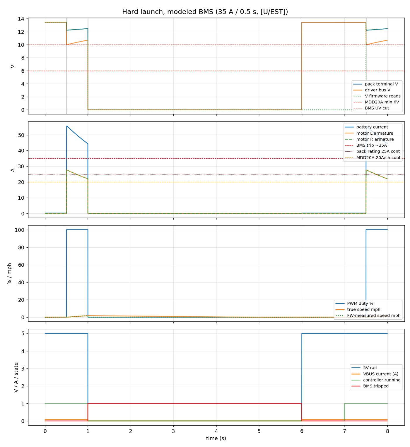
Electrical · hard launch. Pack voltage, bus voltage, motor and battery current from a full-stick start. Where the sag lands relative to every regulator's under-voltage lockout.
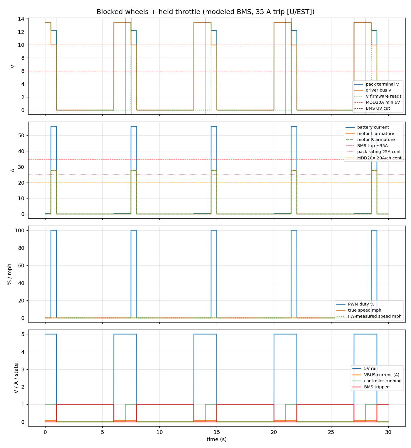
Electrical · BMS cycling. The finding that changed the design conversation: an over-current trip drops the relay, the load disappears, the BMS re-closes, and the whole system oscillates instead of staying off.
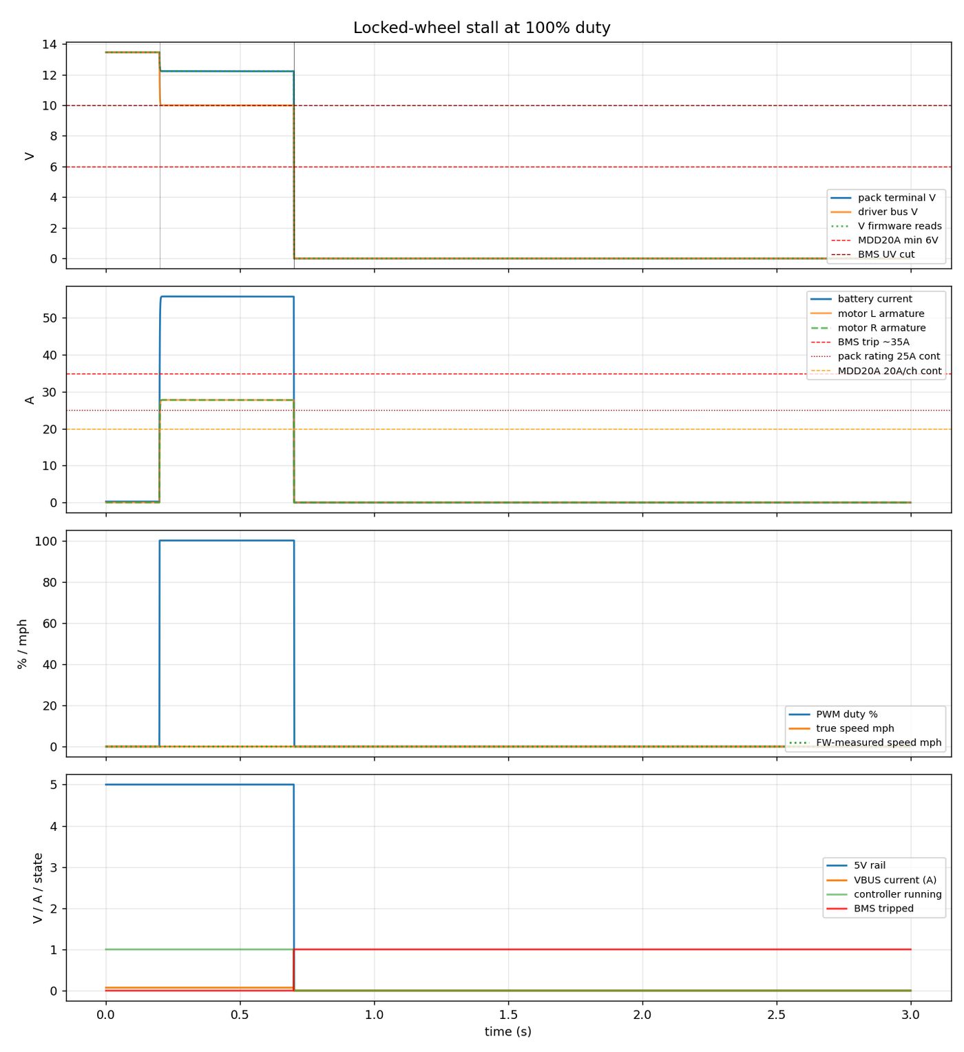
Electrical · full stall. Both rollers blocked at full command. Stall current per motor is ~39 A before pack sag, ~28 A after — against a BMS threshold that is itself owner-attested, not measured, so the verdict is swept rather than asserted.
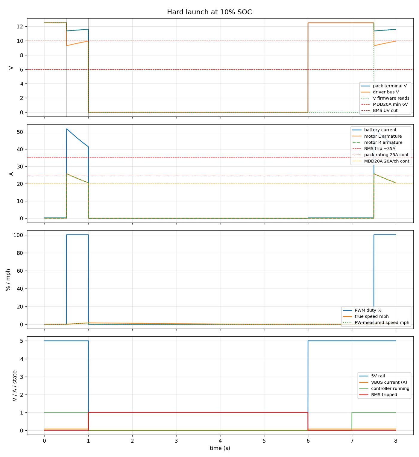
Electrical · low-battery launch. Same launch at 5 % state of charge. The logic rail survives; the question is whether the BMS under-voltage latch fires first.
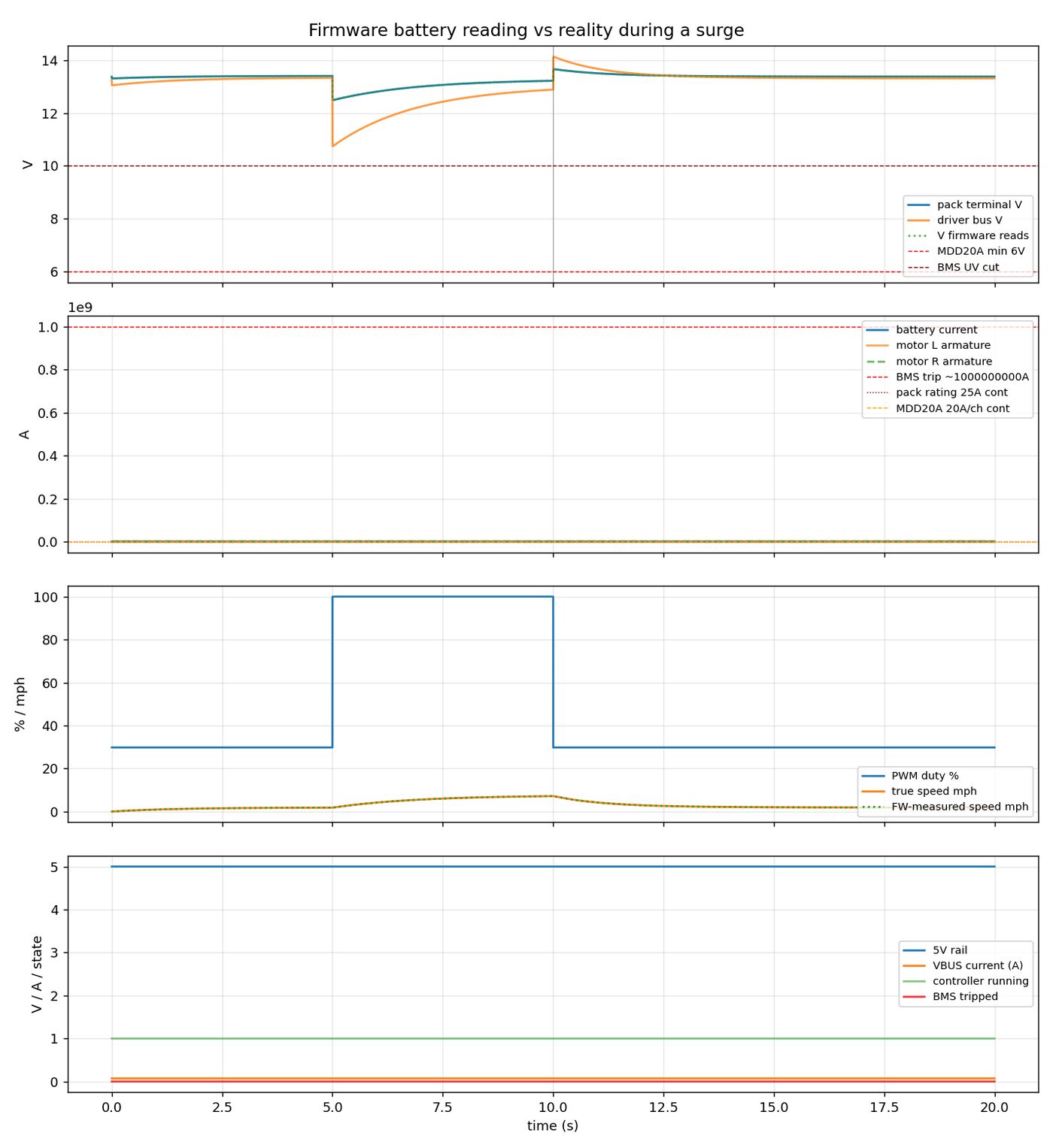
Electrical · battery gauge. The firmware's battery divider taps the raw pack terminal, so the reading sags with load current. What the OLED shows vs what the pack actually holds.
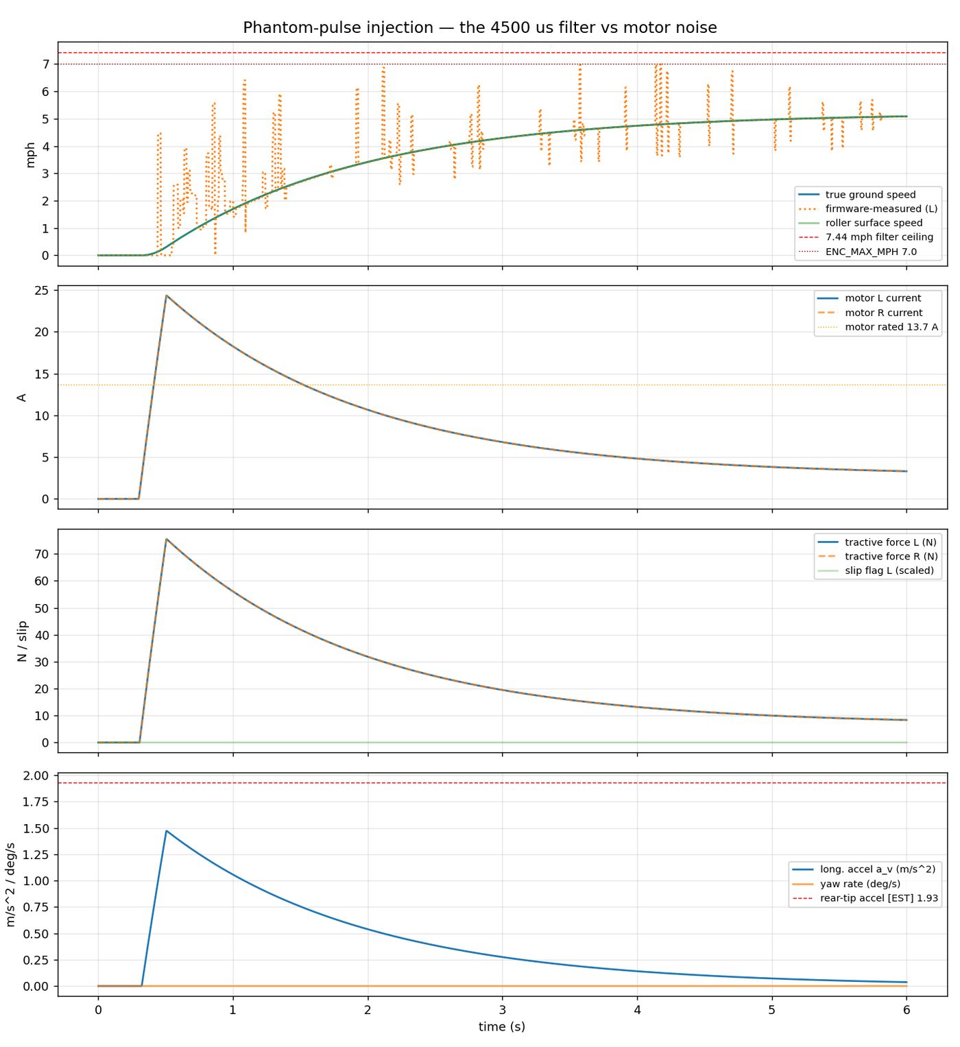
Mechanical · phantom pulses. Motor-PWM noise injects encoder edges tens of microseconds apart; the firmware-measured speed (dotted) spikes to nonsense while true ground speed (solid) climbs smoothly. This is why the 4500 µs filter exists.
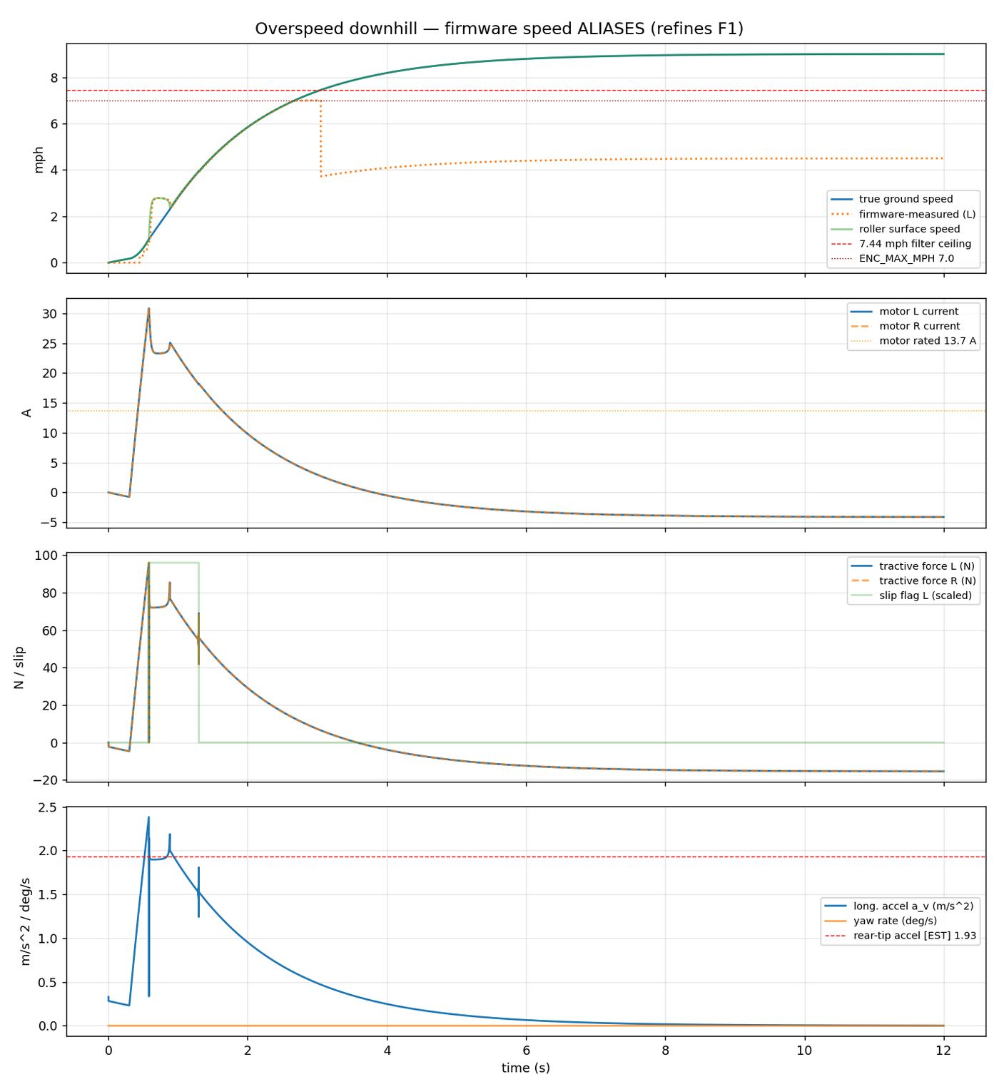
Mechanical · encoder ceiling. The 4500 µs filter implies a maximum readable speed of 7.44 mph on a 1.5 in roller with 8 pulses per rev — and the firmware's own 7.0 mph cap binds first. Reproduced as a regression test in encoder_calc.py --selftest.
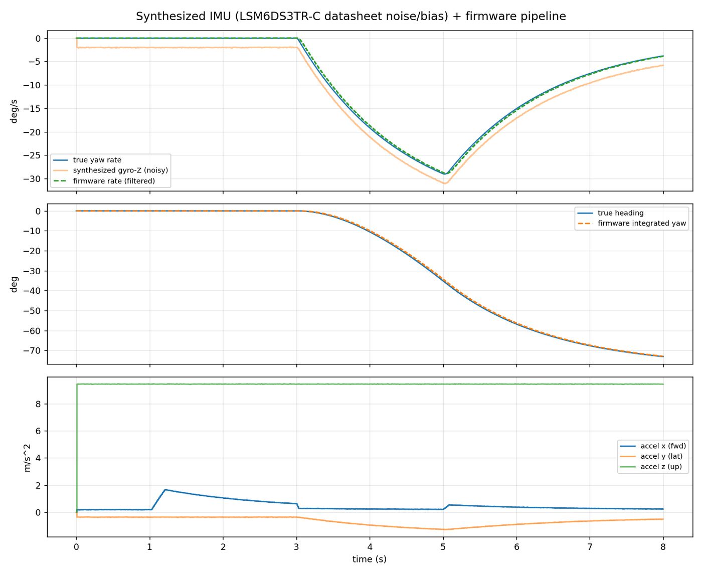
Mechanical · IMU traces. Synthesized gyro and accelerometer signals through the firmware's own bias-trim and integration pipeline, showing how much yaw drift accumulates over a run.
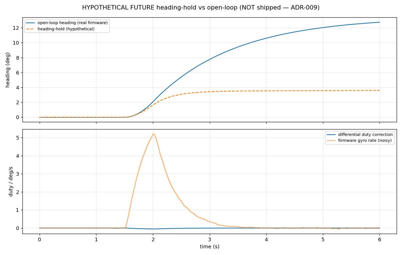
Mechanical · heading-hold. A hypothetical future-firmware controller, explicitly labelled as a demo and not a product claim. This is where the retired closed-loop stack goes once direction-aware encoders are fitted.
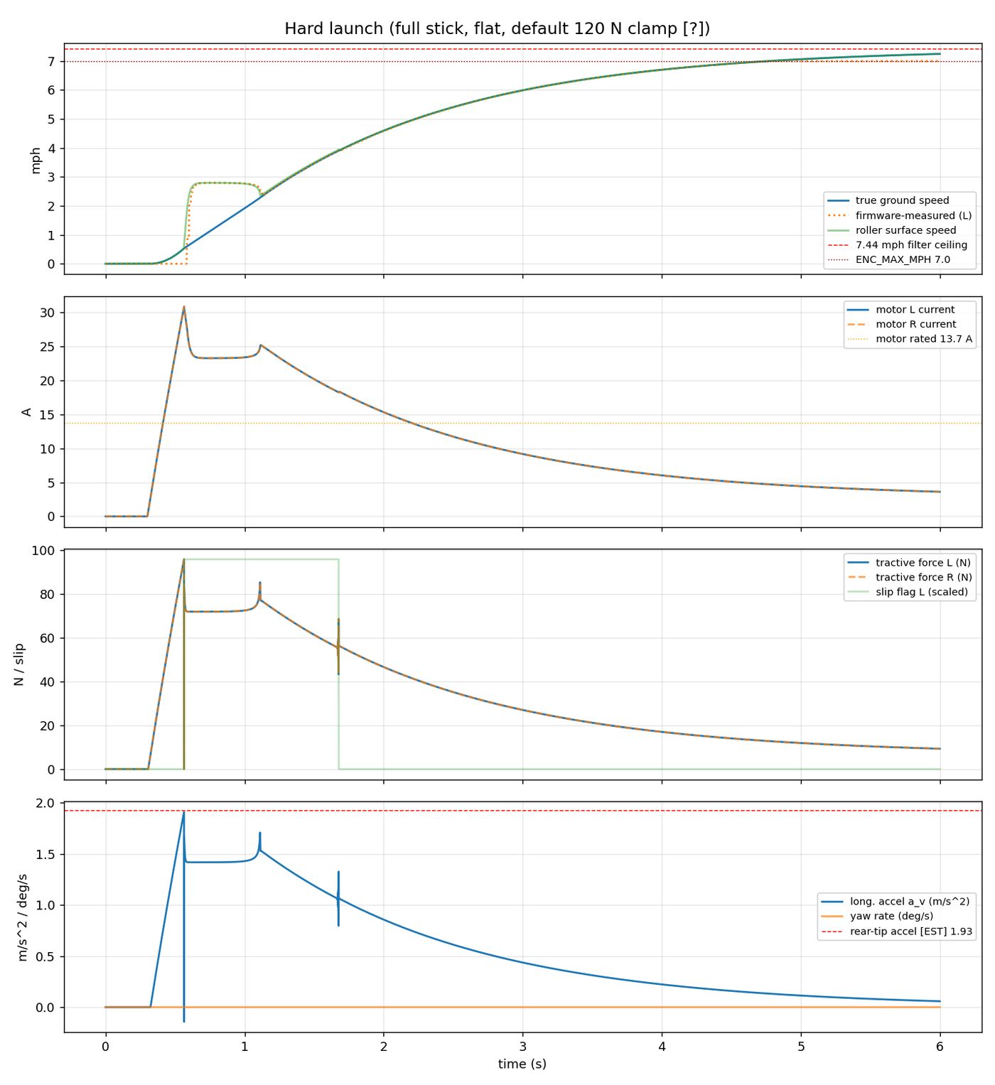
Mechanical · launch dynamics. Tractive force, slip flag, longitudinal acceleration and yaw rate from a hard launch, against the static rear-tip acceleration limit from the moment-balance calculator.
Every constant carries a provenance tag
[M] measured · [F] flashed firmware · [O] observed · [DS] datasheet page-cited · [EST] estimate · [?] nobody has measured it. An untagged number is not established.
Checked against hand calculation
The electrical core reproduces hand calculations to under 0.1 %. The mechanical energy ledger closes within ~3 %. Three stdlib-only calculators ship with --selftest that exits non-zero if the arithmetic drifts.
Adversarially reviewed, bias disclosed
Four independent reviewers — physics, software, empirical validation, docs consistency. The report discloses that the BMS threshold changed after the review ran, and hedges the affected verdicts with a published sweep instead of hiding it.
Path to market
We have opened the conversation with the FDA.
In June 2026 I authored and filed PAWE's Pre-Submission with the FDA as the company's regulatory correspondent — the device description, proposed predicates, a proposed test plan and eleven specific questions. FDA's written response arrived in August 2026 and maps out the testing programme for the 510(k) that follows.
Next up is the bench: the measurements and conformance testing that response calls for. Nothing here claims clearance — it claims a clear plan.
What comes next
- Measure the three numbers the simulations hinge on: roller clamp force, chair centre-of-gravity, cruise and launch current.
- Fit direction-aware encoders and revisit closed-loop control.
- Close the eleven firmware findings from the adversarial review.
- Rewrite the firmware for the cleared product — the prototype code is explicitly not the basis.