Case study 03 · WPI Robotics Engineering · 2023 → 2025
Robots that explore, see, and act.
Three team projects from WPI: a mobile robot that maps an unfamiliar maze, a camera-guided arm that sorts objects by color, and a competition robot designed from first principles. Together, they connect mechanical design, perception, and control.
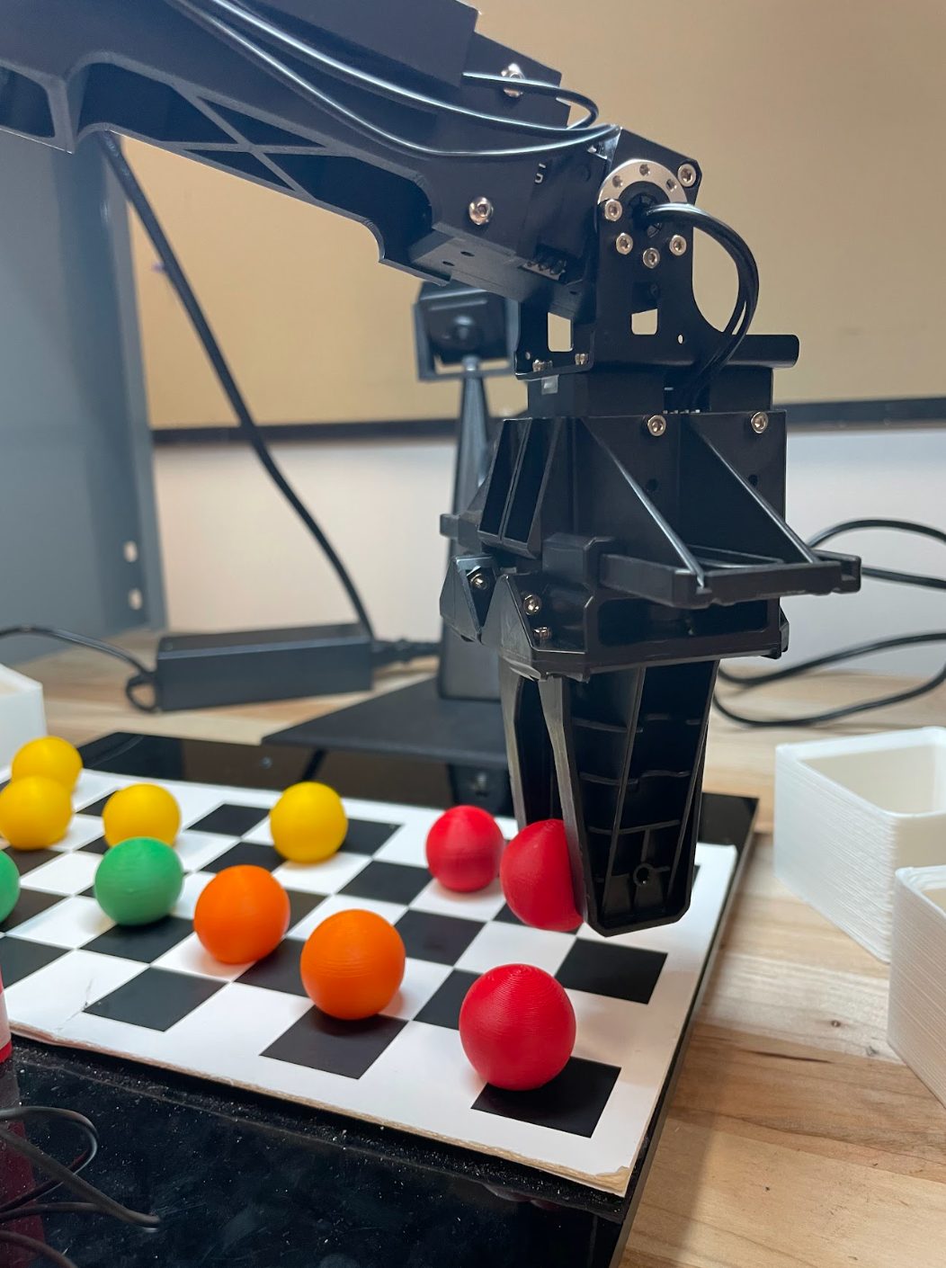
RBE 3002 · Unified Robotics IV · May 2025
Explore an unknown maze, come home, then find yourself again.
A TurtleBot3 Burger, ROS, Python, Gazebo. Three phases: map the field by choosing and driving to frontiers, navigate back to the start, then be picked up, dropped somewhere random, and localize in the map it just built.
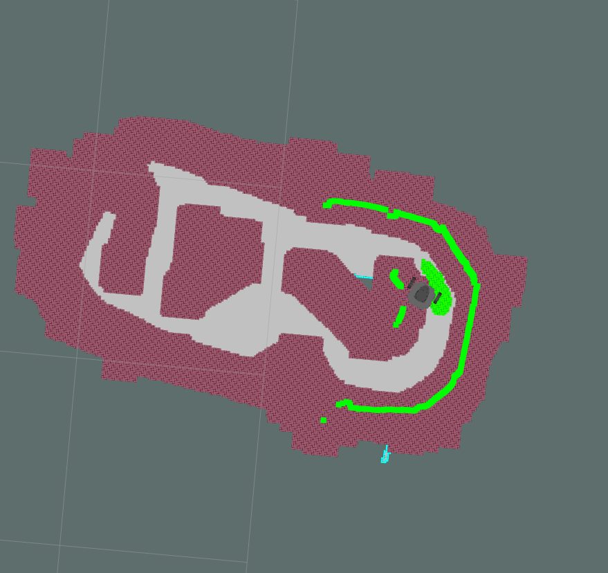
Live map in RViz. Occupied cells inflated into configuration space (red), free space (grey), the robot, and the current frontier cluster and path (green).
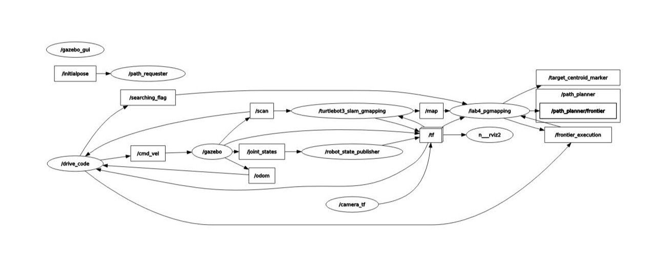
The node graph. gmapping → /map → our frontier node → /target_centroid → path planner → drive node, with AMCL and a custom localizer feeding /tf.
Frontier detection and scoring
The occupancy grid is held as a numpy binary array and processed with OpenCV. C-space by inflating occupied cells. A cell is a frontier when any 8-neighbour is unknown. Contiguous frontier cells are clustered, each cluster scored on distance, size and density, sorted, and iterated until an accessible centroid is found.
A* with a recursive fallback
Safety-checked, optimised A*. If the best centroid is unreachable, the planner walks the ranked list and returns a path to the first that succeeds. That fallback is what carried the run when frontier detection stalled.
Covariance-gated AMCL
A global-localization node spreads particles across the map; a custom node watches AMCL's pose covariance in x, y and heading and accepts the pose only once all three converge — then plans from it. An explicit confidence gate, not a timer.
Result, honestly. All three phases completed in the final demo. Frontier exploration mapped ~95 % of the field; an unresolved bug in the frontier handler stopped the last frontier from being detected, and A* generated the return path as the fallback. The report says so, including that the behaviour was inconsistent enough to make the bug hard to localise.
RBE 3001 · Unified Robotics III
A pick-and-place cell that sees. Calibrate, transform, segment, grasp.
An OpenMANIPULATOR-X arm, a USB camera on a fisheye lens, MATLAB. The arm identifies coloured balls anywhere on the board and sorts them into bins — the same capability pattern an industrial sorting cell runs.
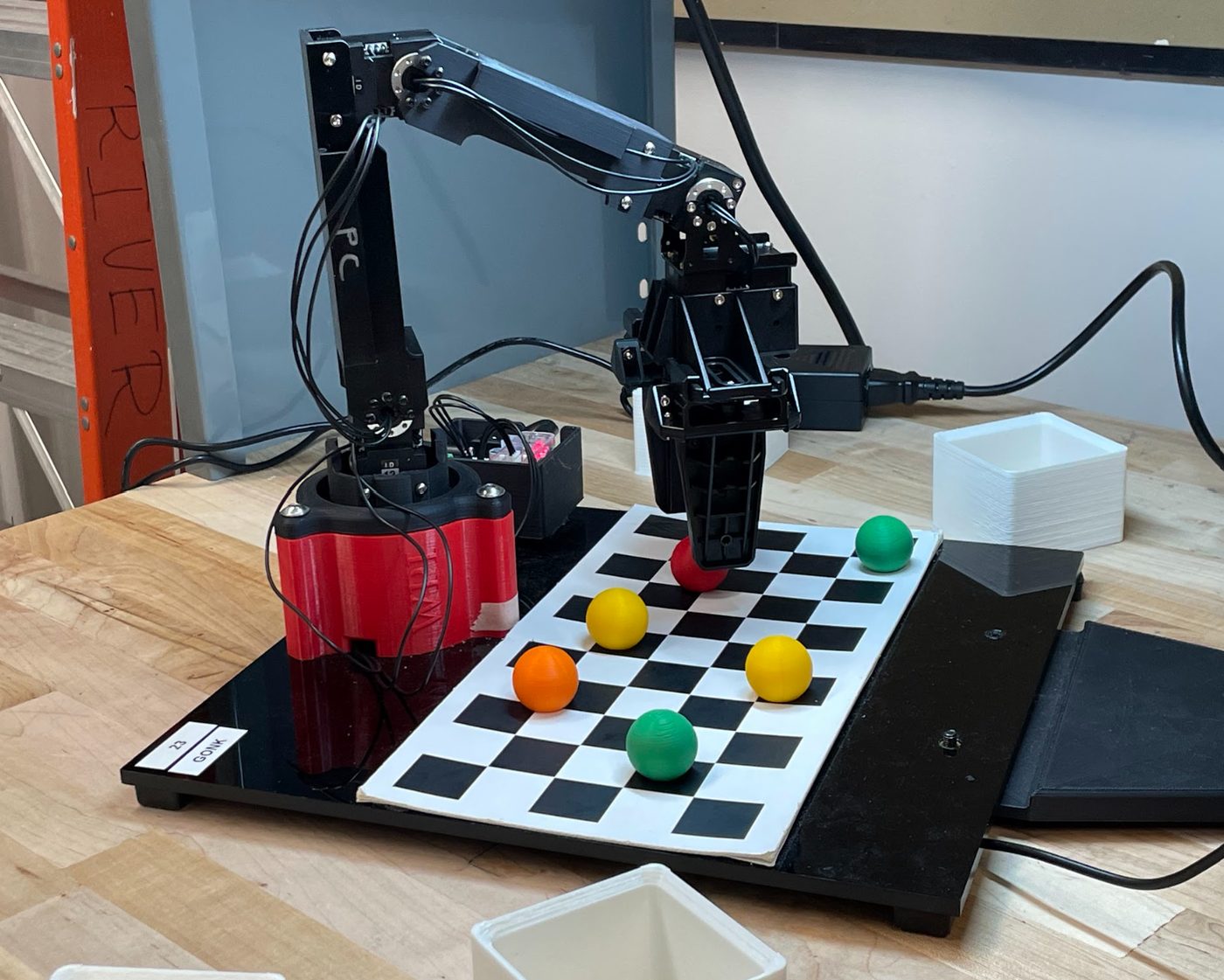
The cell. Checkerboard for calibration and as the world frame; bins for each colour; the camera on a mast to the rear.
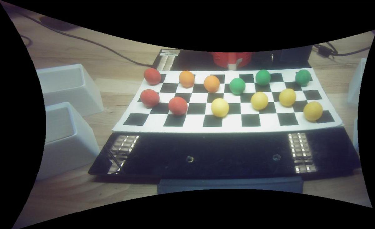
Undistortion. Calibrated with the MATLAB camera toolbox to recover focal length, distortion and pixel scale, then every frame undistorted so the fisheye produces a metrically usable image. The curved black border is the price of a flat world.
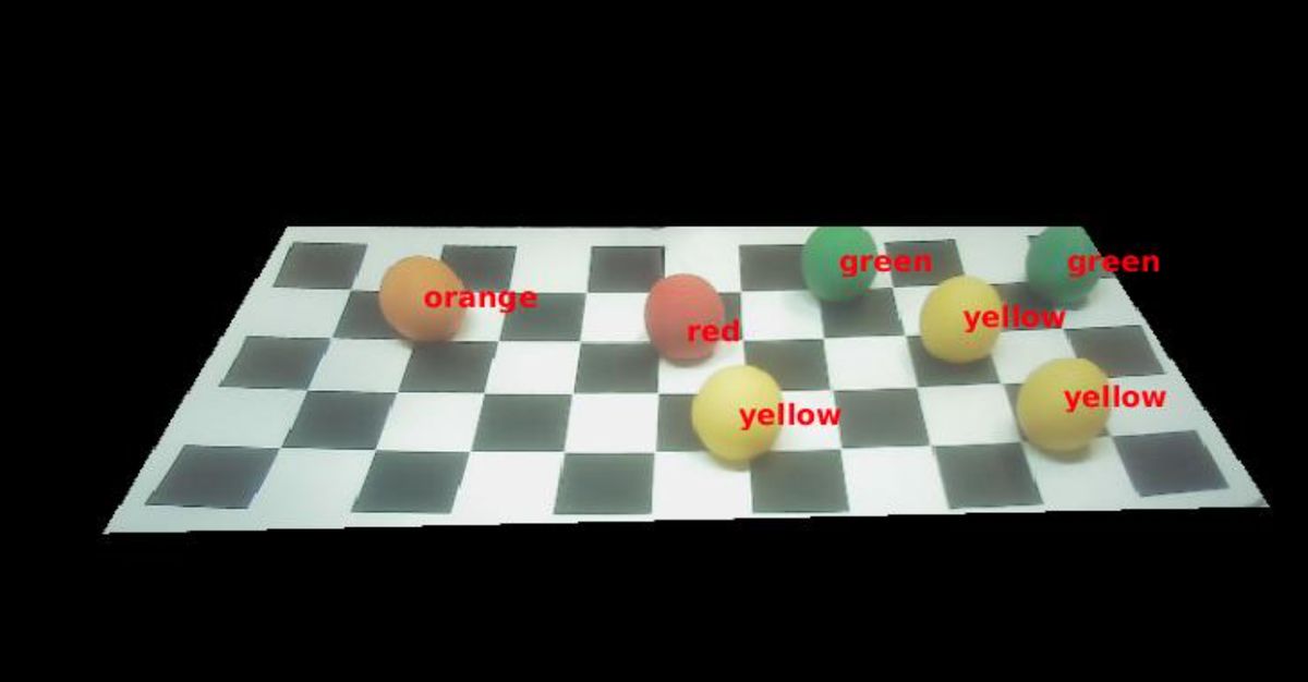
Segmentation. A static mask from the calibration corners removes everything outside the board. RGB → HSV, one threshold per colour wrapped in a swappable ColorMask class, bwareaopen() to drop small blobs, regionprops() for centroids kept one list per colour. The labelled overlay is the debug tool built so filters could be retuned after a camera or lighting change.
Grasp. Pixel → world via pointsToWorld(), then a homogeneous transform to the robot base — translation from the measured robot-frame origin, rotation from the observed frame change. Forward, inverse and differential kinematics from the earlier labs drive the pick, lift, carry and place.
RBE 1001 · Introduction to Robotics · team of four
A competition robot designed on paper first.
Drive up a ramp, lift a four-bar arm, collect and score. Before the first part was cut, the design report worked every subsystem from first principles.
- Drivetrain — speed and tractive effort; stability going up and down the ramp from a moment balance about each axle.
- Lift — four-bar kinematics with free-body diagrams for crank, rocker and coupler; torque requirement against the VEX 11 W motor curve; operation speed.
- Intake — gripper and ball-collector geometry.
- Electrical — sensor selection and placement, maximum current draw.
The analysis methods I learned here later became the foundation for PAWE’s tipping and drivetrain calculators.
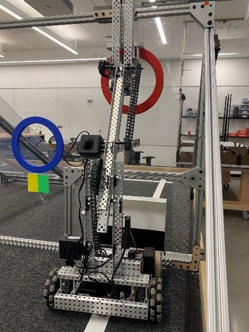
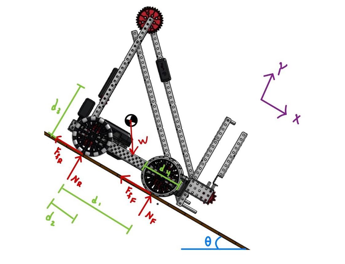
Left: the robot at the field. Right: the ramp free-body diagram — normal and friction forces at each axle, weight at the CoG, dimensions d₁–d₄.
The rest of the sequence
What the coursework covered.
Control Engineering I
Six lab reports and seven problem sets — modelling, root locus, frequency response, compensator design. The theory behind the gain-scheduled PID in PAWE.
Embedded Systems for Robotics
Interrupts, timers, PWM, serial protocols, sensor interfacing — the foundation for the dual-RP2040 firmware.
Digital Circuit Design
Combinational and sequential logic, HDL, timing. Plus the lab section.
Unified Robotics I & II
Mechanical applications in robotics; sensing and perception. Actuation, transmission, sensors, filtering, the labs that led into the arm and the TurtleBot.
Object-Oriented Design Concepts
Java, interface design, patterns.
Calculus III–IV, linear algebra, ODEs, probability
Mechanics, E&M, oscillations and waves.